 "RWS Motorsport" (rwsmotorsport)
01/18/2018 at 15:48 • Filed to: None
 1
1
 11
11|
"RWS Motorsport" (rwsmotorsport)
01/18/2018 at 15:48 • Filed to: None | 1
| 11 |
Mclaren F1 for your time.

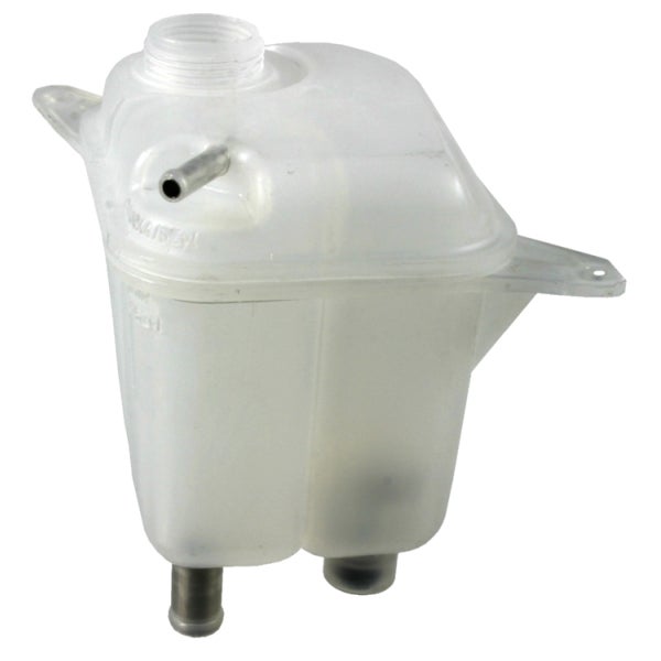
Perhaps the most mundane post in the history of Oppo. But alas, I am trying to design a reservoir of around 2l for a project at work, and think that something along the lines of a coolant expansion tank would be ideal. Lots of inlets, outlets connectors etc. However I cannot for the life of me find a good explanation of how they are made. I’d assumed they were a blow mould but I’m doubting that given all the possible orifices in their design. Could any of you kind folk School me in the ways of Coolant Tank Design? This is the sort of thing I am thinking of:
 jimz
> RWS Motorsport
jimz
> RWS Motorsport
01/18/2018 at 16:00 |
|
it’s injection molded in two halves. the hose nipples are placed in holders in the injection molding die, and the plastic is forced into the die around them locking them in place inside the finished part. then the upper and lower halves of the tank are put into a fixture and vibration-welded together. complex shapes like the threads for the cap have to be done either as a secondary operation, or a more complex die which has surfaces which “slide” into position. otherwise the part would be die-locked.
 diplodicus
> RWS Motorsport
diplodicus
> RWS Motorsport
01/18/2018 at 16:03 |
|
Looks like you’re right. https://geminigroup.net/plastics/blow-molding-regency/products/fluid-reservoirs/ But they aren’t giving out their trade secrets.
 My bird IS the word
> RWS Motorsport
My bird IS the word
> RWS Motorsport
01/18/2018 at 16:03 |
|
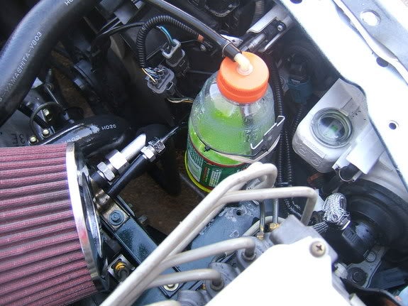
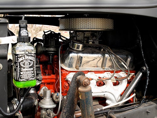
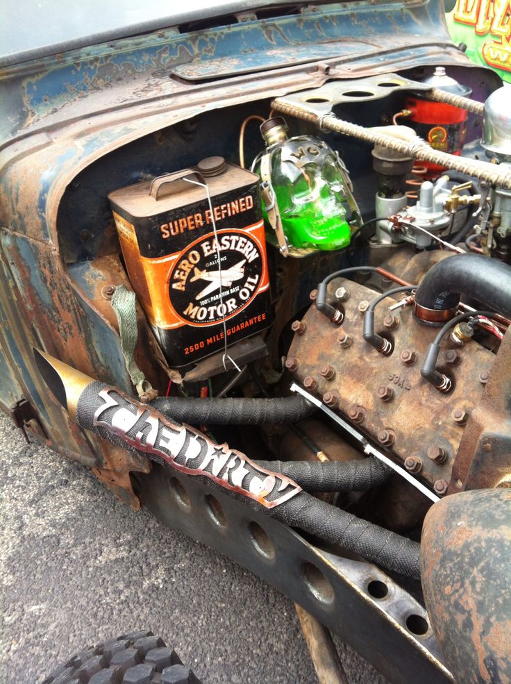
just use any old thing :P
|
RWS Motorsport
> jimz
01/18/2018 at 16:03 |
|
Ah, perfect thank you! Got you, so it’s actually a fairly complex tool then, and still needs ultrasonic welding after the fact to become watertight.
 farscythe - makin da cawfee!
> RWS Motorsport
farscythe - makin da cawfee!
> RWS Motorsport
01/18/2018 at 16:07 |
|
its moulds and liquid plastics where i work (i’d give you a proper name for it... but not my department.. so i never asked... i just refer to that whole department as sica... but thats just the tube cutters)
metal bits will be added by people on final assembly (as will seals and rubbers and wotsits)
(50% chance i misunderstood the question)
|
jimz
> RWS Motorsport
01/18/2018 at 16:07 |
|
vibration/ultrasonic welding:
also note that modern cooling systems use pressurized expansion tanks; they’re at cooling system operating pressure (16-21 psi) unlike the old-style unpressurized overflow tanks.
 46and2aheadofme
> jimz
46and2aheadofme
> jimz
01/18/2018 at 16:10 |
|
This internet comment is concise, informative, helpful, and polite. What is this, opposite day? Hat tip.
 HammerheadFistpunch
> jimz
HammerheadFistpunch
> jimz
01/18/2018 at 16:17 |
|
good oppo right here.
 just-a-scratch
> RWS Motorsport
just-a-scratch
> RWS Motorsport
01/18/2018 at 19:42 |
|
Jimz is probably right about the pictured tank. There are plenty of other ways to do it though. Roto-mold is a good way to get shapes that are difficult to do by injection molding. Also, a roto mold can be simpler or cheaper because the tool only touches the outside of the part.
|
just-a-scratch
> just-a-scratch
01/18/2018 at 20:48 |
|
Can’t find the edit button...
Anyway, if you have a part that will see elevated temperature the roto mold is not going to work well. It’s a method typically used with thermoplastics.
|
RWS Motorsport
> just-a-scratch
01/19/2018 at 03:34 |
|
Thats very useful thanks. It would only being seeing ambient temperature, which we normally say is 0-40 Celsius for our products so that may work. I will look into Rotomould, Thanks!